A common platform for validation of aircraft drag reduction technologies

Geometry

The aircraft proposed for the study, a strut-braced wing configuration, which has a high wing with a high aspect ratio. The strut is attached to the lower belly fairing. The engines are located under the wing. The empennage is of a T tail configuration, as is typical of aircraft of high wing configuration.

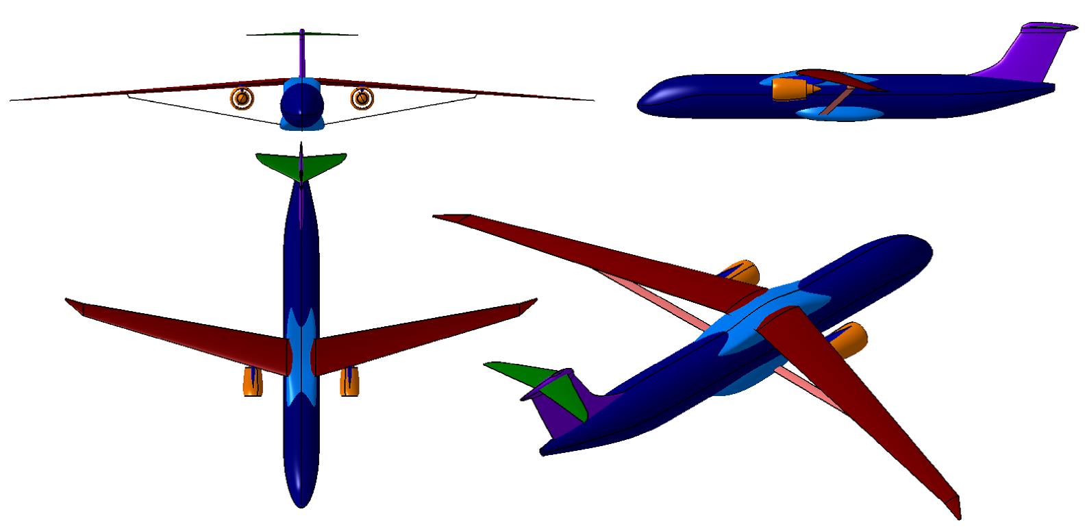
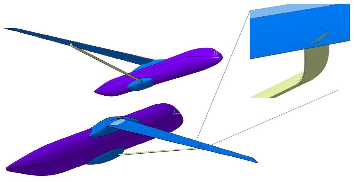
Engines, flap track fairings, pylons and tails have been removed in the final geometry in order to allow us to focus on the area of interest (strut-wing junction) without paying the penalty of the complexity of the full configuration for computational simulations.

This geometry has not been optimized, but prepared on purpose to reproduce wave drag  and interference drag issues in the strut-wing junction at relatively low transonic Mach numbers.
 

Geometry in IGES format is provided in SBW.igs

Flight condition

  • MACH: 0.72
  • ANGLE OF ATTACK:
  • ALTITUDE: 30000 ft
  • ATMOSPHERE: ISA+0
  • REYNOLDS/LENGTH: 7.1 x 10⁶ m-1
  • PRESSURE: 30.08959 kPa
  • TEMPERATURE: 228.71 K
  • Solver parameters for the flight condition can be found in parameters.txt

BOUNDARY CONDITIONS

  • AIRPLANE: non-slip wall or apropriate flow control condition
  • OUTER BOUNDARY: farfield
  • Boundary conditions for each of the surface zones of the mesh are provided in SBW.bmap

Constraints

It is not the intention of the reference model to set “a priori” constraints, but in order to have feasible assessments, we suggest adhering to the following constraints:

  • STRUT GEOMETRY MODIFICATION
    • strut attachment location cannot be modified (both chord and spanwise attachment location)
    • strut thickness can not be reduced
    • the length of the vertical portion of the strut which is attached to the wing cannot be extended, but its shape (tow angle, airfoil profile, etc) are free
  •  
  • WING GEOMETRY MODIFICATION
    • upper wing surface cannot be modified
    • wing twist angle cannot be modified (fixed leading edge and trailing edge)
    • lower surface of the wing can be modified only between the planes
      • y = 14.5 m
      • y = 17.5 m
    • wing thickness cannot be reduced from the reference geometry. Reference lower wing surface cannot be penetrated by the final geometry
  •  
  • ALLOWED GEOMETRY MODIFICATION
    • any region of the strut and lower wing surface that have not been constrained in the previous two sections and between the following two planes
      • y= 14.5 m
      • y = 17.5 m
  •  
  • ALLOWED REGIONS FOR FLOW CONTROL INSTALLATIONS
    • anywhere between the following two planes
      • y= 14.5 m
      • y = 17.5 m
  •  
  • LIFT
    • angle of attack of the airplane can be modified, so that the final solution matches the lift of the initial reference configuration

** Not following these constraints will lead to more complex comparisons which may hamper the identification and assessment of the potential benefit of the technology