General description of the combustor
The test case is a virtual model of low emission gas turbine combustor designed ad-hoc for the numerical study of combustor/turbine interaction [3]. The geometry of the computational domain, shown in Figure 1, was designed for matching the end-walls shape of the MT1 turbine stage [4]. Only the fluid part contained within the combustor inner liner is considered for simplicity.
Two concentric burners are present (Figure 2). A premixed stream of air and fuel (CH4) enters the main burner where a swirl motion is imposed (swirler vanes are not modelled). A second burner (pilot) is present in order to provide flame stability and is located in coaxial position with respect to the main one. In the pilot burner, gaseous fuel (CH4) is injected in cross-flow through four injection channels into a swirled stream of air. Four slots are present along the liner walls to simulate the injection of cooling air. The choice of using CH4 as fuel was dictated by the need of minimizing the modelling effort associated to liquid fuel injection.
The combustor is characterized by a global equivalence ratio of about 0.5. The pilot burner works in non-premixed regime and elaborates about 10% of the total thermal input. An amount of 17% of the total air entering the combustor passes through the cooling slots, while the remaining is distributed between the main burner and the pilot one.
The whole combustion chamber is characterized by the presence of 16 burners in the entire annulus but only a periodic sector of 22.5deg can be considered. The operating pressure is 26.05bar while the total temperature of the combustion products is about 1800K. Operating conditions were selected in order to maintain the same non-dimensional working parameters of the downstream MT1 turbine vane (see [4]), which geometry is maintained unchanged. The original rotational speed of the MT1 turbine stage should be changed to take into account the scaling of inlet conditions.
The leading edge of the turbine vanes should be positioned in correspondence of the “plane 40LE” (Figure 1). Plane 40LE is located 243mm downstream of the inlet section of the main burner. The turbine inlet section (Plane 40), where non-uniform inlet profiles where evaluated in the work of Insinna et al. [3], is located 218mm downstream of the inlet section of the main burner.

Figure 1. Computational domain.
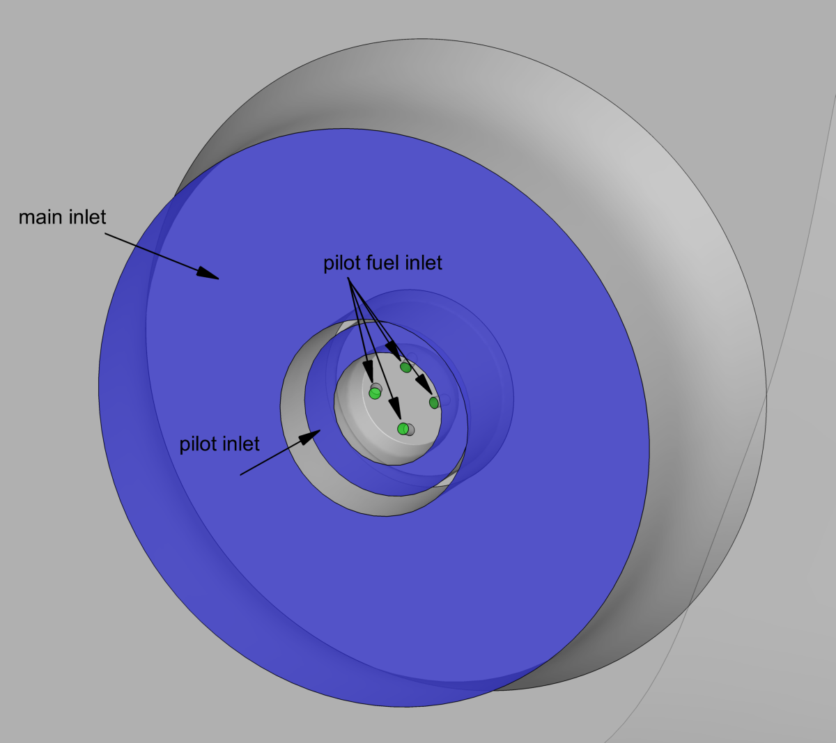
Figure 2. Detail of the burner.
Boundary conditions for the simulation of the combustor
The boundary conditions to be used for the simulation of the combustion chamber are reported in Table 1 in terms of mass flow repartition, total temperature, turbulence intensity, flow direction and mixture composition. For the simulation of the combustor domain, an average static pressure of 26.05bar can be imposed on the outlet section. For main and pilot inlet sections, the components of the unit vector of the flow direction are specified with respect to a cylindrical reference system defined on the burner axis. This latter is positioned at a radius of 255mm with respect to the machine axis.
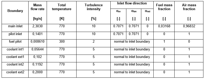
Table 1. Boundary conditions
Computational grid of the combustor
A computational grid for the CFD simulation of the combustor is provided on the portal in ANSYS® Fluent® format (“.cas” with length in meters). It is a hybrid unstructured mesh, composed by about 4.7M elements similar to the one used in the work of Insinna et al. [3]. Local grid refinements are imposed in proximity of the burners, where strong velocity gradients are present. Prismatic elements are used at wall for the discretization of the boundary layer. Such grid is suitable for a RANS analysis but more accurate approaches for turbulence modelling would require higher spatial resolution. The solid model (in IGES and STEP formats with lengths in millimetres) of the computational domain of the combustor is provided on the portal in order to allow the participants to create their own grid.
About the turbine stage
The combustor model was designed from scratch for the numerical study of combustor/turbine interaction as reported in [3]. The geometry of the computational domain of the combustor was designed for matching the end-walls shape of the MT1 turbine stage [4]. The turbine stage geometry is redistributable among the TATEF2 consortium only [5] and then it is not open access. In order to perform an analysis of the full combustor/turbine domain, it is suggested to contact Prof. Thomas Povey (thomas.povey@eng.ox.ac.uk), Dr Kam Chana (kam.chana@eng.ox.ac.uk) or Dr Simone Salvadori (simone.salvadori@unifi.it).