This test case will be based on a given well tested transonic wing, the ONERA M6 wing under the following conditions:
Mach=0.84, Re=11.72 × 10⁶, and Cl=0.2743
A lift constrained optimisation is to be carried out for minimum drag by optimising shock control bumps on the upper surface of the original M6 wing. The original M6 wing should not be parameterised and deformed, i.e. the shock control bumps acts as additive retrofits to the baseline wing. You may use as many or as few bumps as you see fit, with whatever parameterisation methods for your design of the bumps.
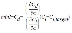
Objective function:
The optimisation is set as minimising drag with lift constrained to satisfy the design lift condition. This can be presented as