The experimental investigation is executed in the S8Ch wind tunnel of the ONERA Meudon Centre. This facility is a continuous wind tunnel supplied with desiccated atmospheric air. The stagnation conditions are near ambient pressure and temperature: pst=0.96 x 10⁵ ± 300 Pa and Tst=300 ± 10 K. It is constituted by a rectilinear channel having a test section with a height of 120mm and a span of 120mm (in full nozzle configuration). The test section side walls and upper wall are equipped with high quality glass windows to allow using optical techniques, mainly to detect the location of the boundary layer transition.
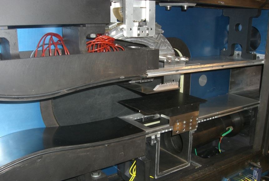
Figure 1 shows the test set-up with the Mach 1.6 full nozzle configuration, the unit Reynolds number being around 14 x 106 m-1 for this Mach number. The shock generator wedge (with its displacement device) has been installed on the upper wall of the test section. The flat plate under study is mounted above the lower wall and the re-generated boundary layer will interact with the shock-wave. The location of the flat plate has to be movable in both the longitudinal and vertical directions to allow the study of the boundary layer behaviour with respect to the shock impingement. The leading edge shape of the flat plate is designed to take into account of the bluntness effect on the boundary layer transition and to allow the shock to stay attached: the flat plate thickness is equal to 3mm; its leading edge radius is around 20µm and the bevel angle is equal to 6°. The flat plate length, equal to 200mm, is dimensioned by both the location of the natural transition and the side wall boundary layers contamination, and its span is equal to the test section width (120mm). In order to perform IR (Infra-red) thermography measurements, the material of the flat plate is chosen as Inox 304L. The surface finish is achieved by hand work using emery cloth and the averaged rugosity (Ra) is estimated at 0.8µm. Moreover, the expansion fan emanating from the shock generator trailing edge influences the flow on the study plate far downstream of the region of interest. Lastly, the test set-up is located in such a way that the leading edges of the two plates remain in the Mach number rhombus, in order to avoid any perturbation of the flow.
Suction through the upper and lower walls of the test section is necessary to remove the incoming wind tunnel floor boundary layer and to avoid blockage effect of the flow due to the presence of the flat plate and the shock generator wedge. Auxiliary pumps and high pressure air supply are available to perform this fluidic control of the flow (see the open areas, the cavity and the duct on Fig. 1). The suction mass flow rate necessary to maintain the secondary flow supersonic is equal to 120 x 10-3 kg/s under the flat plate and 50 x 10-3 kg/s above the shock generator wedge.
Emphasis is placed on parameters influencing the viscous interaction, namely:
- The location of the theoretical (i.e., for a non-viscous flow) shock impingement point by translating the flat plate. This location is characterised by its abscissa XI from the study plate leading edge, or in a non-dimensional form, by the Reynolds number computed with XI. For the five longitudinal positions of the flat plate under study, the corresponding values of XI lead to a related Reynolds number range of: 0.42 < ReXI (x 106) < 1.12.
- The shock wave intensity, represented by the value of the flow deflection through the incident shock. For each position of the flat plate (and corresponding value of XI), the angle of attack α of the shock generator wedge is increased from 0° to 5°.
Figure 2 shows a sketch of the test set-up with the flat plate longitudinal positions and the open cavity under the flat plate to control the secondary flow. Several vertical positions of the flat plate have been tested in order to check if the secondary flow is staying supersonic thanks to flow control. When the flat plate is elevated to Z = 40mm from the test section floor, the range of longitudinal locations of the flat plate is increasing from X = -33.95mm to X = 11.05mm.

So, the retained location of the flat plate into the test section is as follows (see the origin of the coordinate system on Fig. 2): X = -11.45mm (P3 position: ReXI = 0.78 x 10⁶) to avoid perturbation from the reflection of the Mach wave emanating from the plate leading edge, and Z = 40mm to avoid blockage effect under the plate.
Two values of the angle of attack of the shock generator wedge are selected: α = 2.5° and 5°. The first configuration is producing an oblique shock of moderate intensity and the second one corresponds to a strong shock intensity leading to a massive boundary layer separation. The leading edge of the shock generator wedge is located near the test section entrance plane, at X = 3mm and Z = 84.5mm.