Governing equations
The governing system of equations is the 3D Reynolds-averaged Navier-Stokes system with a constant ratio of specific heats of 1.4 and a constant Prandtl number of 0.72. Dynamic viscosity is prescribed with the Sutherland law.
The choice of turbulence model is left up to the participants; recommended suggestions are :
- Spalart Allmaras model
- Wilcox k-omega model
- k-omega SST model
EARSM is an additional option.
Geometry
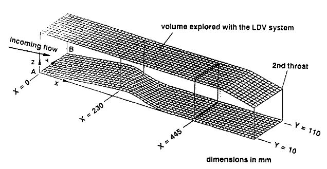
The geometrical definition of the channel is shown in Fig. 1. It consists of a converging-diverging section with three flat faces and the fourth face (lower wall) bearing a swept bump.
The section is 120 mm wide and 100 mm high in the inlet plane. The upstream part of the bump is flat and inclined at 7° with respect to the horizontal. This first portion is followed by a contour of variable slope, beginning with a circular convex part with a radius of 180 mm. The two circular arcs are defined so as to ensure slope continuity at the points where they interconnect as well as at the points where they come to contact with the rectilinear upstream and downstream parts.
The 3D effect is achieved by sweeping the bump crest line from the upstream flow direction.
The maximum height of the bump is 20 mm and its length is equal to 355 mm. The generation is cylindrical downstream of the crest line (see [1] for a more complete definition of the channel geometry).
Flow conditions and boundary conditions
Under these conditions the boundary layers are fully turbulent well upstream of the interactions.
In the subsonic outlet the static pressure is prescribed and adjusted to obtain the experimental location of the leading of the oblique shock. This adjustment can depend on the turbulence model used. The ratio between outlet static pressure and inlet stagnation pressure is about 0.65.